|
The harder you work, |


|
KSimulink - Digital Simulation |
|
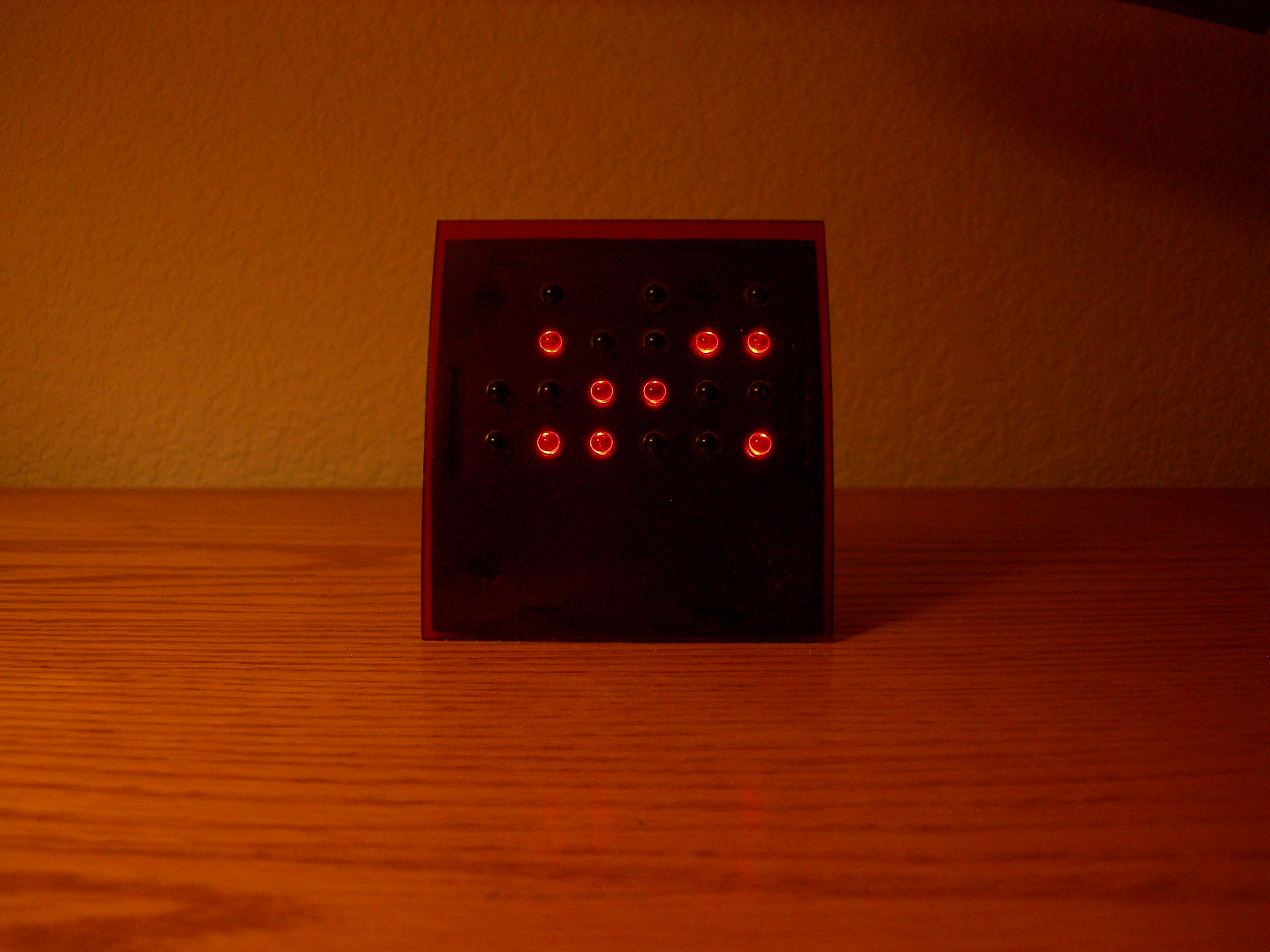
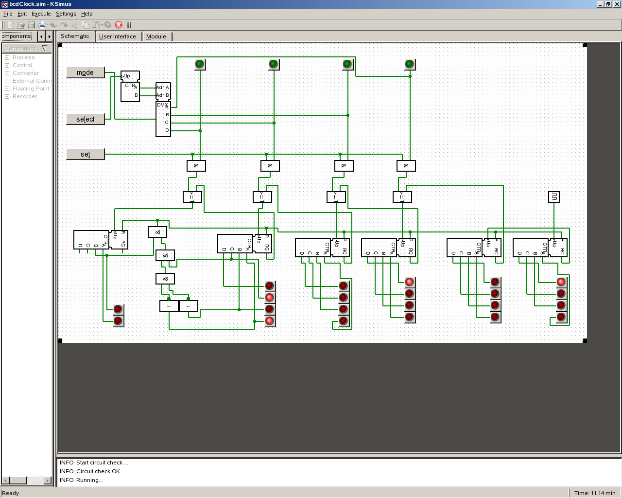
The project demonstrates basic digital circuit design of a non-VonNeumann architecture using standard SSI and MSI components (decade counters, 2-bit counter, D flip-flops, demultiplexers, AND, OR, a few buttons and some LEDs). This project simulates a simple sequential digital logic circuit that was inspired by the Binary Coded Decimal desk clock pictured here. The circuit simulator used is KSimulink, which runs under Linux distributions that use KDE. I’ve included two screen captures of an active simulation. The first depicts the “user interface” displaying 5:07:56. The second screen capture depicts the operational circuit schematic displaying 5:08:08. My design differs slightly from the commercial product as I’ve added green LEDs to indicate the “time setting mode”. (Note: The KSimulink application identifies AND gates as ‘&’, and OR gates as ‘>=1’.) While the circuit implements the desired functionality, I may redo this project at a later date using a CPLD or FPGA, which would yield a less expensive implementation. |
Digital Circuit Design |
|
Simulating a BCD clock |


|
www.MichaelDWelch.net MichaelDWelch@(no-spam)acm.org www.linkedIn.com/in/MichaelDWelch 303-920-9749 remove (no-spam) |